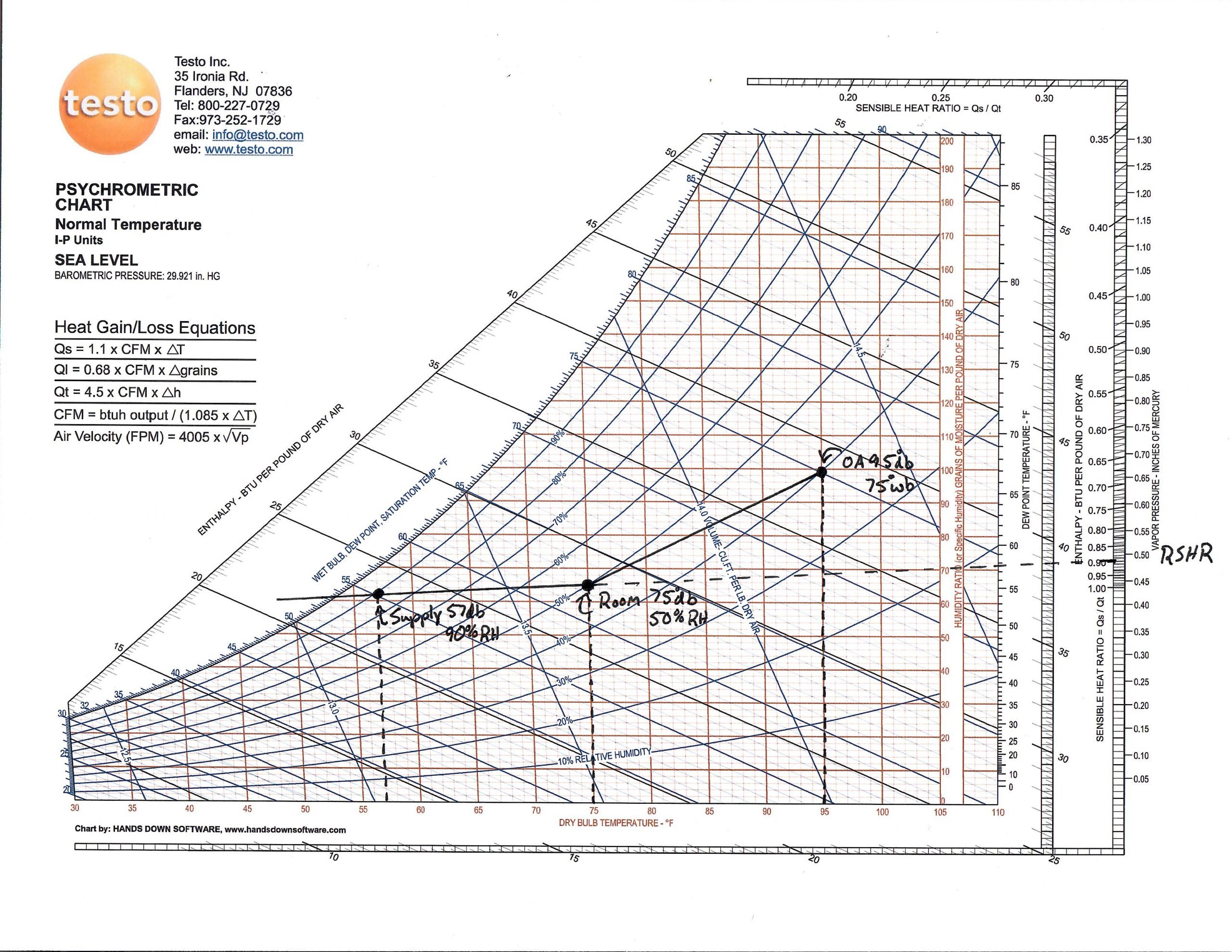
Room Sensible Heat Factor Line

What Is Rshf Gshf Ershf Bpf
Https Www Airah Org Au Content Files Technicalpublications Draft Da09 Section 8 Applied Psychrometrics Pdf
Question Of The Week 08 Using The Sensible Heat Ratio Protractor Youtube

Refrigeration Air Conditioning Ppt Download

Concept Of Rshf Hshf And Eshf
.png)
Module 14 The Psychrometrics Of Air Conditioning Systems Cibse Journal
Sensible heat formula for hvac engineers where does q 1 08 cfm δt come from.
Room sensible heat factor line.

Conditioning Of Moist Air Ppt Video Online Download

Apparatus Dew Point Room Sensible Heating Factor Gshf For Gate Hindi Hindi Psychrometric Chart For Gate Refrigeration And Air Conditioning Part 3 Unacademy
.png)
Module 11 The Psychrometrics Of Hvac Sub Systems Cibse Journal
Https Www Ias Ac In Article Fulltext Reso 017 02 0117 0138
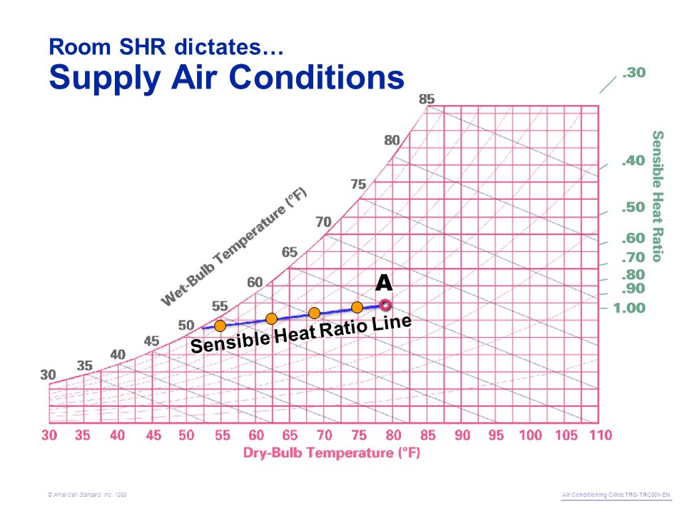
A Trane Air Conditioning Clinic Psychrometry Air Conditioning Clinic Trg Trc001 En C American Standard Inc Ppt Download
Psychrometrics Archives Hvac School
Https Hvac Eng Com Psychrometric Processes

Psychrometric Analysis Revision Of Principles Central Plant Ppt Download
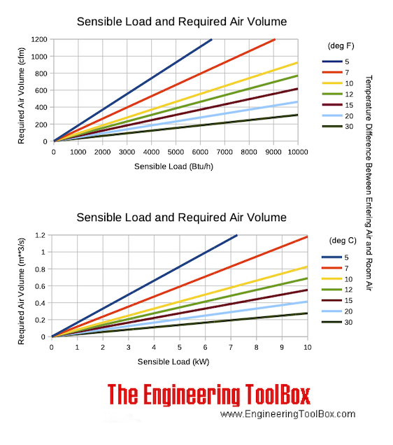
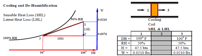
Cooling Load Latent And Sensible Heat
Psychrometrics Energy Models Com
Http Www Kau Edu Sa Getfile Aspx Id 91926 Fn Space 20air 20conditioning 20 Pdf
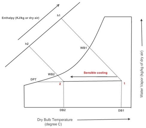
Psychrometric Processes Sensible Cooling Sensible Heating Of Air Bright Hub Engineering

Bypass Factor And Sensible Heat Factor In Hindi Hindi Psychrometric Chart For Gate Refrigeration And Air Conditioning Part 3 Unacademy
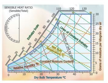
How To Use A Psychrometric Chart Lines And Curves Bright Hub Engineering
Source : pinterest.com
